SprutCAM Sketch
Sketch allows to easily create and manipulate parametric 2d geometry which one can use in Machining to define parts, fixtures, job assignment of 2d and 2.5d milling, turning, Wire EDM and other operations.

Creating a sketch
Click
 to create a sketch in the XY plane of the current coordinate system.
Select a geometry entity (e.g. a planar face) and click
 to create a sketch in the plane of the selected entity.
Select curves or edges, or a folder containing curves, right click and select Convert to Sketch command from the popup menu to convert selected curves to a sketch.
Drafting tools
Draft/Trim
![]()
The Draft/Trim tool is used to draw connected contours consisting of lines and arcs. There are three drawing modes available, which can be switched with the Space key on the keyboard.
line,
tangent arc,
tangent line.
To draw a line tangent to an arc or a circle, hold the shift key and click on the arc.
For convenience the tool allows not only drawing of new lines, but also trimming of existing geometry. To trim just press and hold the left mouse button over the empty space and drag the mouse cursor over the element you want to trim away. A red line will be drawn, and the element will be highlighted. Then release the mouse button. The element will be deleted.

Trim
![]()
The tool is used to delete unnecessary geometric entities.
Box by two points
![]()
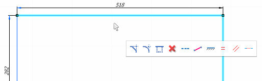
The rectangle is specified with two corner points. It's created with two dimensions, one can change by simply clicking on the dimension value.

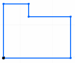
Box from center
![]()
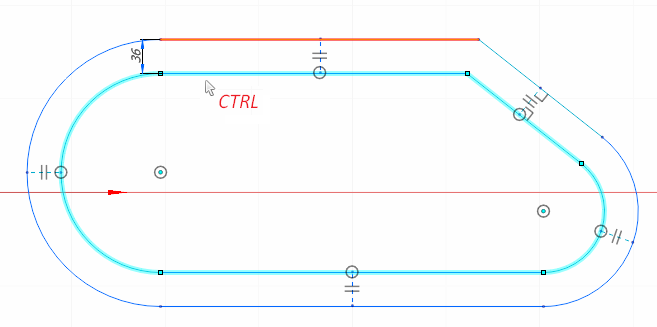
The rectangle is defined by its center and one of the corners. For convenience two additional symmetry lines are created, so when changing the box dimensions, both sides of the box move in the opposite direction. Plus, one can easily rotate the box by unlocking the angle of the horizontal symmetry line.


Circle
![]()
There are three ways of drawing a circle all available in one tool.
Circle by center and radius
The first click defines the center of the circle. The second click specifies the radius. Hold the Shift key and click on a highlighted line or an arc to create a circle tangent to the highlighted entity. Type the circle diameter on the keyboard and hit Enter instead of the second click if you know the diameter. Type 'R' if you want to specify the radius instead of the diameter.
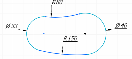
Circle by tangents
Hold Shift and click on a point, a line or an arc, (it should highlight) to create a circle tangent to this entity. To completely define the circle you have to click on 3 entities, or click on 2 entities and enter the circle diameter or radius with the keyboard. If you choose to enter the radius instead of the diameter, an arc will be created instead of a circle.
Multiple circles with same radius
One can easily create multiple circles with same diameter by holding the Ctrl key and pointing the center points of the circles with single clicks.
Dimension
![]()
The dimension tool allows to easily create linear, angular, diametrical and radial dimensions all in one place. The type of the actual dimension is determined by entities you click on.
The horizontal, vertical and parallel linear dimension of a single line is created with two clicks, the first one to be on the line itself, the second one over the empty space to specify the position and the orientation of the dimension line as well as the dimension caption.
The linear dimension between two entities is created with two clicks on those entities and one click over the empty space to specify the position and/or the orientation of the dimension line and the dimension caption.
The angular dimension between two lines is created with two clicks on those lines and one click to define the position of the dimension line and the caption.
The radial/diametrical dimension is created with one click on the arc/circle and one click over the empty space.
After creating a dimension, one can change its value by clicking on it and typing on the keyboard or mouse-wheeling. The sketch will be rebuilt automatically to accommodate the change.
Import curve
![]()
The import curve tool allows to import curves from the 3d Model into the sketch. Click the import curve button, then click on the curves or edges you want to import in the graphic view.
Editing tools
The geometry editing is done by selecting entities and dragging them with the mouse or choosing commands from the contextual action bar, or firing keyboard commands.
Selecting entities
Single click selection. Left click on an entity to select it. Hold Ctrl to select multiple entities. Or you can select entities by right clicking on them. In this case you don't have to hold the Ctrl key for multiselect.
Box selection.
Double click selection. Double click on an entity to select all similar entities. You can select all circles, or all fillets with the same radius. You can select all colinear lines, or all chamfers of the same size.
Chain selection. You can easily select a contour or its part by clicking on one entity of the contour with the Right mouse button and swiping the mouse over the entities you want to select.
Deleting entities
Just hit Del on the keyboard to delete the selected geometry.
Moving entities
To move selected geometry into another position just drag it with the mouse. All the selected points will be moving synchronously with the one you drag, the other entities will be rebuilt in order to satisfy the dimensions and the constraints applied to the sketch. When dragging a point, or a line to which dimensions are attached by the blue arrows, those dimensions become temporarily unlocked. This is made for convenience sake, so one could change the sketch dimensions by simple drag and drop without using the keyboard.
Moving entities with detaching
Holding Shift while dragging entities detaches the selected geometry from the not selected geometry at selected points. So, for example, if you want to separate one side of a rectangle from the rest of it, select the whole line with both its two end points, hold Shift and drag the line to a different position.

Copying entities
Hold Ctrl while dragging selected entities to make a copy .
Offsetting entities
If you drag selected entities by a line instead of a point, then the entities will be offset by normal instead of just being displaced. If you want to create a new contour equidistant to the selected one just hold Ctrl while performing the drag. In addition to the contour itself a dimension and synchronization lines will be generated between the source and the new geometry, so one can change the offset value after the offset is done.
Additional commands
Increase/decrease PMI font
![]()
One can increase or decrease the size of the dimension elements, such as arrows and captions with the two buttons.
Insert an image
![]()
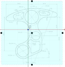
To simplify the task of converting a paper drawing into a parametric sketch a raster image can be inserted into the sketch. Just click the Open button, and select the file with the image in the explorer. Then place the image in the desired position, by selecting it by its dashed side and mouse-dragging. Then move the center point of the image to the position of where the scale center should be and change the size of the image by dragging the side points. If you want to change the aspect ratio of the image, hold Shift while dragging the side points.
Open/Save Sketch
![]()
It is possible to save and load a sketch into/from an .gsf file.
Contextual action bar
When selecting sketch entities on the screen the contextual action bar appears. It offers actions applicable to the selected entities.
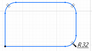
Chamfer, rounding
![]()
The commands generate chamfers or roundings in all selected points. The first generated chamfer/rounding is generated with a dimension, the rest are constrained to be equal to the first one. This allows to easily change the size of the fillets after they have been created.


Defeature
![]()
The operation deletes selected segments from a contour and heals the hole by extending neighboring segments. You can delete chamfers, roundings, grooves and other features this way.
Construction line
![]()
The command switches the type of selected entities between main/construction. Construction entities are drawn with a dashed line. They are used to define geometrical relations between other entities, but otherwise have to be invisible to the system. Examples of construction lines include symmetry lines, aligning lines and other.

Lock/unlock position
![]()
The command fixes or frees the selected entities. Fixed entities do not change their position when changing the sketch dimensions. Fixed entities are drawn in black. Completely defined entities are drawn with a thick line, the entities that have some degree of freedom are drawn with a thin line.

Dimension a point, a line or an arc
![]()
For a horizontal or vertical line adds a linear dimension from the fixed point of the sketch to the line.
For a point adds one or two dimensions (horizontal and vertical) from the fixed point to the selected point, depending on the number of degrees of freedom of the point.
For an arc or a circle adds a radial/diametrical dimension.
Lock/unlock line angle
![]()
Lock/Unlock the angle of selected lines. Lines with locked angle do not change their angle when editing the sketch. They are drawn in blue. The lines with an unlocked angle are drawn in green. By default the angle of all horizontal and vertical lines is locked.
Lock/unlock arc radius
![]()
Lock/Unlock the radius of selected arcs/circles. Arcs with a locked radius are drawn in blue. The arcs with an unlocked radius are drawn in green.
Align line
![]()
The command makes the selected line horizontal or vertical, depending on what it is closer to. For two selected points the command creates a construction line between those two points and makes it horizontal or vertical.
Make equal
![]()
For selected lines the command makes them of equal length, for selected arcs or circles the command makes them of equal radius.
Make parallel
![]()
The command makes selected lines parallel to each other.
Make collinear
![]()
The command makes the selected segments to lie on the same line.
Make perpendicular
![]()
The command makes the selected lines perpendicular to each other.
Make symmetrical
![]()
For the selected three lines, the function finds the middle line and makes the remaining two symmetric with respect to it.
For the selected one line and two points, the function makes the points symmetrical with respect to the line.
For the selected one line and two arcs, the function makes the position of the centers of the arcs symmetric with respect to the line.
Make tangent/incident
![]()
For the selected two points, the command makes them incident
For a selected point and a line, the command makes the point to line on the continuation of the line.
For a selected point and an arc, the command the point to lie on the circle of the arc
For two selected arcs/circles or for a selected line and an arc, the command makes two entities tangent.
Constraints
Constraints are displayed on the screen using icons. Some constraints, such as equality, are present on the screen all the time, others are drawn only when the elements to which they are applied are selected. If for some reason the constraint is not satisfied, it is drawn in red. When you hover the mouse pointer over the constraint, both the constraint itself and the entities to which it is applied are highlighted. Double-clicking on a constraint selects all related constraints. Selected constraints can be removed by pressing the Del key on the keyboard.