Machine axes control panel
Machine axes control window allows you to watch and modify the current values for all machine / robot coordinates. To show this windows you need to click ![]() button on the main toolbar. It is helpful when analyzing tool path in simulation mode, when constructing of manual approaches or when determining the initial position of the machine to calculate the technological operation.
button on the main toolbar. It is helpful when analyzing tool path in simulation mode, when constructing of manual approaches or when determining the initial position of the machine to calculate the technological operation.
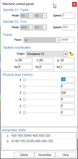
Visually, the window is divided into several areas. The number of panels and their content may vary depending on the particular machine configuration.
The topmost panels display rotation mode and speed of the machine spindles. Number of records corresponds to the number of spindles defined in machine schema. Text fields can take the following values.
RPM/CSS - rotation mode - constant angular speed (rotations per minute) or constant surface speed (m/min or f/min).
M3/M4/M5 - direction of rotation - clockwise or counterclockwise. M5 - spindle is stopped.
Spindle speed.
The <Spatial coordinates> panels display the current spatial coordinates of the tool tip relative to the current workpiece CS, Machine base CS, Current tool CS or any selected object CS (It will display for the two latest cases). The number of panels is determined by the number of machine channels.
The first field can contain values G0, MPM and MPR. They define the feed type and feed units. G0 - tool moves on rapid feed, MPM - normal feed in mm/min or in/min, MPR - feed is given in units per revolution (mm/rev or in/rev).
The second field contains the feed value.
X, Y and Z fields define the tool tip coordinates in the current workpiece coordinate system.
RX, RY, RZ and RW fields contain the values that determines the tool orientation relative to the current workpiece coordinate system. Depend on the machine configuration they are either the components of the tool normal vector or the different kinds of the Euler angles or the components of quaternion.
The <Physical axes (joints)> panel contains a list of linear, rotary and auxiliary machine axes that are defined in the machine schema. Minimal, maximal and zero positions for each physical axis defined by the machine manufacturer and do not depend on the current workpiece coordinate system.
At the bottom of the window is the <Remember state> panel. It displays a list of stored states of the machine and a few buttons to control the elements of the list. The <Remember> button copies the current machine state (the values of each machine axis) and add it to the list. The <Delete> button allows to exclude the selected machine state from the list. The <Clear> button removes all states from the list. To switch the machine to one of the stored states double-click it in the list. Using the <Remember state> feature is helpful while constructing of manual transitions on machines with complex configuration of the axes (such as 6-axis articulated robots).
See also: